Product Introduction:I. Product OverviewTheSwitched Reluctance Motor control cabinet is the core control unit of the switched reluctance motor speed control system (SRD). It works in conjunction with the switched reluctance motor to perform functions such as motor startup, shutdown, operation, speed regulati
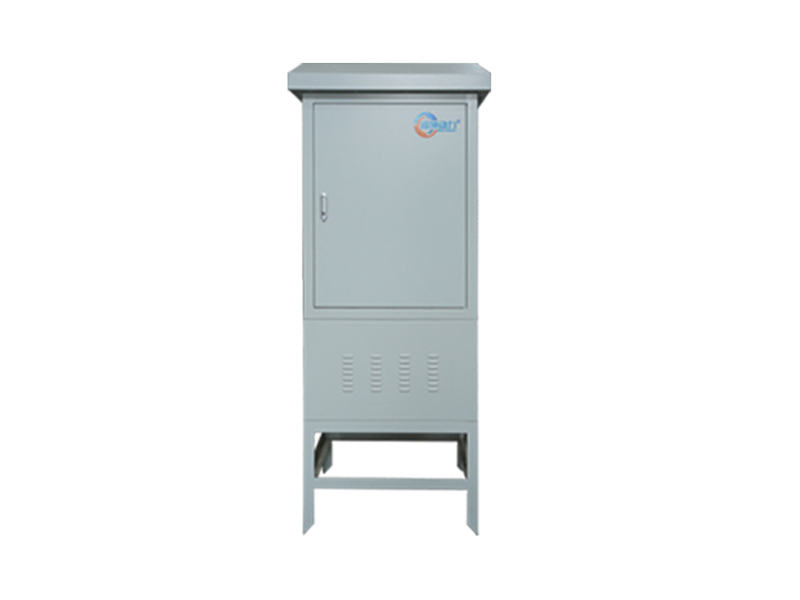
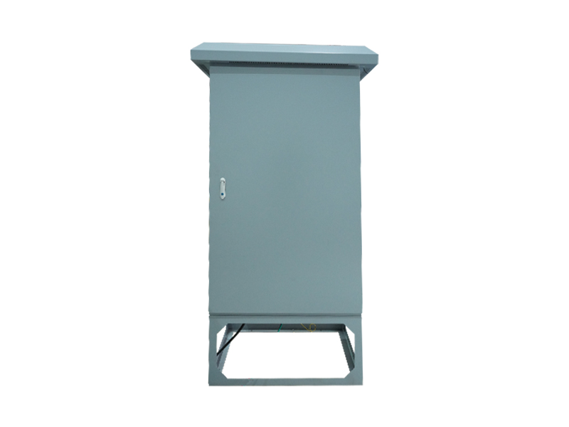
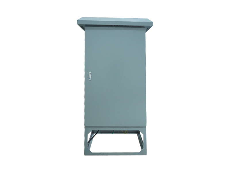
The Switched Reluctance Motor control cabinet is the core control unit of the switched reluctance motor speed control system ( SRD). It works in conjunction with the switched reluctance motor to perform functions such as motor startup, shutdown, operation, speed regulation, protection, and electromagnetic braking for reverse rotation of the pumping rod. The design is compact, the operation is intuitive, and the protection functions are comprehensive, making it suitable for use in outdoor oil and gas field operations.
The control cabinet is installed in a vertical position. It has a sturdy structure and excellent dust and heat dissipation properties. It is suitable for installation in well-ventilated areas free from corrosive gases, where vibrations are less than 0.6G. Sufficient space should be reserved around the cabinet for cooling and maintenance purposes.

It contains a control panel and precision electronic components. Various motor control functions are implemented through software. The core control logic is based on modern advanced control theories, supporting four-quadrant operation. This enables optimal operation state regulation, such as maximum output and highest efficiency.
Is equipped with an AC voltage meter, DC voltage meter, and touchscreen parameter display module to provide real-time operational data. The control panel features a start button, stop button, and speed adjustment knob for easy on-site operation. The speed adjustment range is 40-200 Rpm, with a precision of ±1 Rpm.

Schematic Diagram of Switched Reluctance Control Cabinet
The junction box contains four types of core terminals. Wiring must be performed by professionals. The ground wire should be short and reliable. The common terminal for output signals is not grounded. It is strictly prohibited to connect the power cord to the output terminals. The control cabinet has undergone voltage withstand testing before leaving the factory, and users are not allowed to repeat this testing. The specific terminal configurations are as follows:
1.AC input terminals (R, S, T): Connect to a 380V three-phase AC mains supply
2.Motor control output terminals (A, B, C, D): One-to-one connection with motor terminals
3.Position sensor input connector (SEN_INPUT): Connects to the motor position sensor output
4.Electromagnetic brake output terminals (E1, E2): Connect to the electromagnetic brake input (do not connect the intermediate terminal)

The panel has7 stage status display functions, providing accurate feedback on the entire device operation process:
1.Pre-charging phase: Maintain for 60 seconds until all power indicator lights are on
2.Pre-charging completion and preparation phase: Ready for operation
3.Shutdown phase: Displays operating current, rotational speed, voltage turn-on ratio, torque, position sensor status, etc.
4.Operation phase: Real-time display of current, rotational speed, voltage activation ratio, torque, and position sensor readings. The rotational speed can be adjusted using a knob.
5.Braking phase: Displays the braking voltage activation ratio and reverse rotation speed, which gradually decrease to 0 as the braking process continues.
6.Manual parameter setting phase: Enter management permission password to set rotation speed and parameters
7.Fault alarm display phase: Provides precise information about the fault type for easy troubleshooting
Provides protection against five core types of faults, with rapid response and effective protection. Once the protection mechanism is activated, the system enters a braking state. After the braking ends, fault information is displayed, requiring manual or remote recovery to prevent equipment damage: 1.Sudden current spikes or short circuits in power component output: Tripping value 200A, response time < 1 microsecond
2.Motor Real-time current overload for Phase B/D: Trip value 120A, response time 4 microseconds
3.Motor average current overload: Trip value 60A, response time 3 seconds
4.Power component overheating: Trip value at 80°C, response time 3 seconds
5.Motor position sensor malfunctions: continuous errors triggering the protection mechanism 3 times
Regular maintenance ensures the long-term stable operation of the control cabinet. The following points require special attention:
1.Check if the terminal screws are loose to ensure reliable wiring
2.Clean the dust from the heat sinks and PCBs. Use dry compressed air at a pressure of 4–6 kg/cm² for cleaning<#>6<#.
3.Check the operating status of the cooling fan. It needs to be replaced after 20,000 hours of cumulative operation<#>6<#.
4.Monitor the condition of aluminum electrolytic capacitors. Replace them promptly if discoloration, unusual odors, or bulging occur.
Through standardized maintenance, it can work in conjunction with switched reluctance motors to achieve efficient, energy-saving, safe, and reliable drainage operations.

Go Top

 Hotline:
057983718080
Hotline:
057983718080
 Scan
Scan



 Location: